How To Use The Modulino Distance
Learn how to get the most out of your Modulino Distance.
The Modulino Distance is a modular sensor that measures distance using Time-of-Flight (ToF) technology, making it perfect to add precise distance sensing and depth mapping to your projects!
The Modulino form factor is shaped with two QWIIC connectors and the I²C protocol integration, allowing the connection and programming of multiple modulinos in a very simple way. In addition to the QWIIC's connectors, the Modulinos also expose solderable pins that can be used in multiple ways and make them compatible with boards that are not QWIIC compatible.
General Characteristics
The Modulino Distance is capable of measuring distances using Time-of-Flight technology. Take a look at the following table to know more about its measuring ranges:
| Parameter | Condition | Minimum | Typical | Maximum | Unit |
|---|---|---|---|---|---|
| Range | Distance Measurement | 1 | - | 1300 | mm |
| Resolution | - | - | 1 | - | mm |
| Operating Temperature | - | -30 | - | 85 | °C |
Sensor Details
The VL53L4CDV0DH/1 sensor from STMicroelectronics is the core component of this module. This ToF sensor natively supports digital communication (I²C), meaning it connects directly to the I²C bus on the module without requiring additional conversion circuitry.
| Parameter | Condition | Minimum | Typical | Maximum | Unit |
|---|---|---|---|---|---|
| Field of View | - | - | 18 | - | ° |
| Wavelength | Laser Emitter | - | 940 | - | nm |
The default address for the Module is:
| Modulino I²C Address | Hardware I²C Address |
|---|---|
| 0x52 | 0x52 |
Note: Since the address cannot be changed on this Modulino specifically, using two or more identical modules on the same I²C bus will result in address conflicts and cause communication issues.
Pinout
The pinout for the Modulino Distance is shown below. Please note that the exposed solderable pins are directly connected to the QWIIC connectors using the same I²C interface.

1x4 Header (Sensor GPIO)
| Pin | Function |
|---|---|
| GND | Ground |
| 3V3 | 3.3 V Power |
| GPIO1 | Digital Output |
| XSHUT | Xshutdown |
- GND: Ground – Ground connection for power and signal reference.
- 3V3: Power – 3.3 V power supply input.
- GPIO1: Digital Output – General purpose digital output pin.
- XSHUT: Xshutdown – Shutdown control pin for the sensor.
1x4 Header (I2C)
The pinout for the Modulino Buzzer is shown below. While the recommended connection method is via the QWIIC connectors, this solderable header provides a connection option when using the modulino with a non-QWIIC compatible board.
| Pin | Function |
|---|---|
| GND | Ground |
| 3V3 | Power Supply |
| SDA | I²C Data |
| SCL | I²C Clock |
Depending on the board connected to the modulino, the I²C pin names to program it may differ. Please check the board tutorials on your modulino's compatible board or the Modulino library to learn more.
Power Specifications
The board is typically powered by +3.3 VDC when using the QWIIC interface as per the I²C standard.
| Parameter | Condition | Minimum | Typical | Maximum | Unit |
|---|---|---|---|---|---|
| Supply Voltage | - | - | 3.3 (QWIIC) | - | V |
| Current Consumption | Active measurement mode | - | 24 | 40 | mA |
| Operating Temperature | - | -30 | - | 85 | °C |
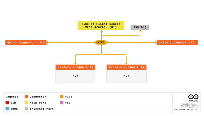
The module additionally includes a power LED that draws 1 mA and turns on as soon as it is powered. J1 (Qwiic connector), J2 (Qwiic connector), and the headers all share the same power branch. The power distribution of the module is therefore as follows:
Schematic
The Modulino Distance uses a simple circuit, as shown in the schematic below:
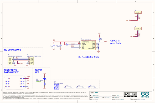
The main component is the VL53L4CDV0DH/1 sensor (U1), which handles distance measurements using Time-of-Flight technology, as well as I²C communication.
You can connect to the I²C pins (SDA and SCL) using either the QWIIC connectors (J1 and J2, this is the recommended method) or the solderable pins (J4). The board runs on 3.3 V, which comes from the QWIIC cable or the 3V3 pin on J4.
There's also a small power indicator LED that lights up when the board is on.
You can grab the full schematic and PCB files from the Modulino Distance product page.
How To Connect Your Modulino
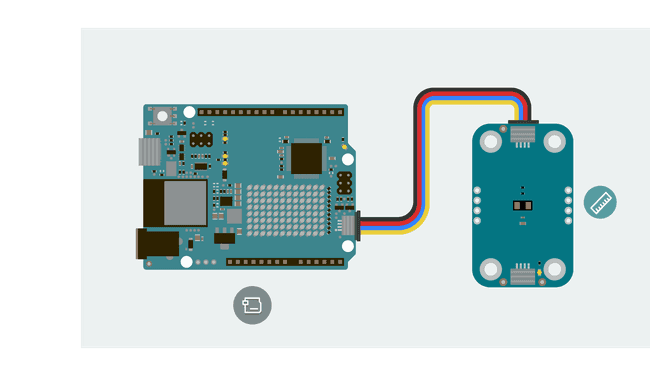
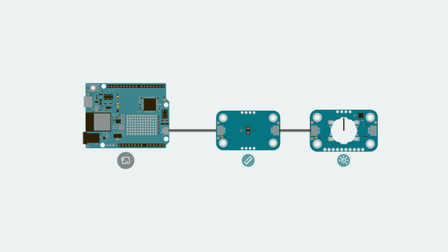
The easiest and most reliable way to connect your Modulino is through the QWIIC Connect System. It’s plug-and-play, uses standard I²C, and makes it easy to join multiple modules. If your board supports QWIIC, this is the recommended way to go.
Note that the dedicated I²C pins will differ from board to board meaning it is always a good idea to check your specific model.
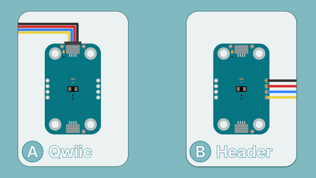
QWIIC Connector
Whenever available, the QWIIC Connect System is the preferred method. Connecting to the Modulino is extremely simple, just use a standard QWIIC cable to connect your board to either of the QWIIC connectors on the Modulino. Because the cable and connectors are polarized, there is no need to worry about accidentally swapping connections.
QWIIC is a plug-and-play I²C Connect System that uses standardized 4-pin connectors:
- GND
- 3.3 V
- SDA (Data)
- SCL (Clock)
The Modulino features two QWIIC connectors, which are internally connected in parallel. This means you can daisy-chain multiple modules easily by connecting additional QWIIC cables between them.
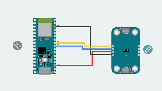
Solderable Header
When QWIIC is not available, you can use the exposed solderable pins on the module. You can solder pins to the unpopulated pads; just remember the pinout provided in this guide to connect to the right pins of your board.
Daisy-Chaining Multiple Modulinos
Regardless of whether you connect the first Modulino via QWIIC or through the solderable pins, you can still take advantage of the extra QWIIC connector to daisy-chain additional modules. Each Modulino includes two QWIIC connectors wired in parallel, allowing you to connect one module to the next in a chain. As long as each module is configured with a unique I²C address, they can all communicate on the same bus. This approach keeps your setup clean, modular, and expandable without adding extra wiring complexity.
The number of modules you can connect will depend on what modules you are chaining together, as this system allows for multiple sensors from different manufacturers to be added. Also, the cables you use for these connections will play a significant role in the setup's performance. Ensure your cables are correctly connected and capable of handling the required data transfer. Each module should have a unique address on a chain if you plan to address them individually. Multiple modules with the same address will cause conflicts on the I²C bus.
How To Use Your Modulino
Installing The Modulino Library
You need the official Modulino library available here to use the Modulino Thermo.
With the Arduino IDE you get some tools that make adding a library easier. To learn how to install the IDE please visit our page.
After opening the IDE, a tab should be visible on the left. Press the book icon for "library" as highlighted in the image.
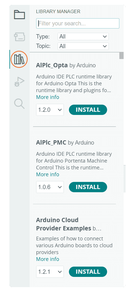
The process should look like this:

A message will appear after the installation is successful.
Getting Distance Data
Getting data from the sensor is fairly simple using the
Modulino
: Checks if new distance data is available.available()
: Retrieves the measured distance from the sensor (default in cm).get()
: By default the Modulino library usesModulino.begin();
if your connection is in a different Wire you will have to edit it, check here (by default the Modulino library usesWire1
if your board model has a different pinout for the dedicated I²C pins you might have to edit it. More information on Wire can be found here) for the library's hardware compatibility. More information on Wire can be found here.Wire1
Here is an example sketch of how to implement these functions to acquire data and show it using the serial monitor:
1#include "Modulino.h"2
3// Create object instance4ModulinoDistance distance;5
6void setup() {7  Serial.begin(9600);8
9  // Initialize the Modulino system and distance sensor10  Modulino.begin();11  distance.begin();12}13
14void loop() {15  if (distance.available()) {16    int measure = distance.get();17    Serial.println(measure);18  }19  delay(10);20}
Troubleshooting
Sensor Not Reachable
If your Modulino's power LED isn't on or the sensor isn't responsive, first check that the board is properly connected:
- Ensure both the board and the Modulino are connected to your computer, and that the power LEDs on both are lit.
- If the issue persists, make sure the Qwiic cable is properly clicked into place.
Library Not Installed Properly
If you encounter an issue with the
#include "modulino.h"- Check your IDE to ensure the library is installed and up-to-date.
- Re-install the library through the Library Manager.
Inaccurate Values
If the sensor values are not accurate, make sure:
- The sensor lens is clean and free from dust or obstructions.
- All exposed electronics are not touching any conductive surfaces, as this could interfere with readings.
- The object being measured is within the sensor's detection range.
Conclusion
The Modulino Distance is a digital Time-of-Flight distance sensor that communicates over I²C and follows the Modulino form factor. It includes standard Qwiic connectors for quick, solderless connections and easy daisy-chaining with other modules. Paired with the Modulino library, it makes accessing distance data straightforward, allowing you to focus on experimenting or building your system logic. It's a small, reliable module suited for both quick tests and longer-term setups.
What Is Next?
Now that you've learned how to use your Modulino Distance, you're all set to integrate it into your projects!
- Create a parking assistance system that provides audio feedback as objects get closer, similar to car parking sensors.
- Build a theremin-like musical instrument that changes pitch or volume based on hand movements in front of the sensor.
- Design an automatic dispenser that activates when hands are detected beneath it (for soap, sanitizer, etc.).
Suggest changes
The content on docs.arduino.cc is facilitated through a public GitHub repository. If you see anything wrong, you can edit this page here.
License
The Arduino documentation is licensed under the Creative Commons Attribution-Share Alike 4.0 license.